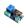
ESP8266 5V 10A DC 7-30V Wireless WIFI Network Relay Module U8 Smart Home IOT
| SKU | ELE-COM-075 |
| Weight | 20 g |
| Ships from | Cardiff, UK |
Description:
ESP8266 5V 10A DC 7-30V Wireless WIFI Network Relay Module Board U8 Smart Home
This WiFi relay module carries a ESP8266 WiFi module and micro controller.
It will send the serial port instructions to the cell phone APP and Implementation within the local area network (LAN) for wireless control relay.
Features:
Onboard Module: ESP8266 WIFI Module,can connect 5 client at the same time on the mode of AP
Working Method: Mobile phone equipped with Wifi module
Mobile phone and wifi module equipped with: one router,and control the relay by APP
Onboard Relay: 5V,10A/250V AC 10A/30V DC relay
| Pin | Description |
|---|---|
| GND | 0V |
| TX | Transmit |
| RX | Receive |
| 5V | 5V |
| Terminal | Description |
|---|---|
| NO | Open until triggered |
| COM | Common |
| NC | Closed until triggered |
| IN- | 0V |
| IN | 5V |
The function and characteristics
1. Onboard ESP8266 wifi module,In AP mode, it can be connected by 5 clients at the same time;
2. Wifi relay module has two work modes:
(1)cell phones carry on the wifi module directly;
(2)cell phone and wifi module carry on the same router;
3. Transmission distance:
(1) In the open environment, the maximum transmission distance is 400m when the cell phone carry on the wifi module directly ;
(2) when the wifi module and cell phone carrying on the same router ,the transmission distance depend on the routers signal intensity;
4. Onboard 5v, 10 A / 250 v AC 10 A / 30 v DC relay, absorb 100000 times continuously;
Module with diode effusion protection, short response time;
The board function description:
IN ,IN-: 5V power input;
TX ,RX and GND: serial port debug pins;
Instructions:
1. Onboard the ESP8266 wifi module has three work modes: STA (client), AP (hot), STA AP( hot client), According to the work mode of wifi relay module to choose the corresponding mode of ESP8266 wifi module .
2. Module need configuration by serial debugging software and USB to TTL module send serial command , TX ,RX ,GND pin of USB to TTL module connect to RX ,TX ,GND pin of ESP8266 relay module,and IN ,IN- connect to DC5V power.
3. The default Baud rate of wifi module maybe is 115200 or 9600,you can send AT command change it,such as: AT CIOBAUD=115200. I recommend you use 115200 in general conditions, but you should change it to 9600 when you use cell phone control the relay(because the Baud rate of on board MCU STC15F104W is 9600).
Please note:
1. Wifi relay module needs to be reconfigured if restarted
2. ESP8266 wifi module has a timeout mechanism, when the cell phone haven't sent commands to the ESP8266 wifi module over a period of time (default is 180s) , the ESP8266 wifi module will kick off your cell phone, you can send
AT CIPSTO = < time > on the PC to modify this time (time range 0-7200), such as: AT CIPSTO = 3600.
3. If it not return OK and just return what you have sent commands when you use USR-TCP232-Test-V1.3 configure the wifi module,you can press the ENTER before send commands
4. If it no response when you use USR-TCP232-Test-V1.3 configure the wifi module, maybe the baud rate is incorrect, You can try 115200 or 9600. but when you use cell phone control the relay, you must make sure the baud rate of wifi module is 9600(send AT CIOBAUD=9600 can change it), because the baud rate of onboard MCU(STC15F104W) is 9600
5.If you want to use a computer to control relay directly(baud rate is 9600), you can unplug the ESP8266 wifi module,and TX ,RX ,GND pin of USB to TTL module connect to TX ,RX ,GND pin of wifi relay module, IN and IN- connect to DC5V power. Send serial command (A00101A2 open relay; A00100A1 closed relay,command format must be hex) with serial debugging software on the PC to control the relay.
6.If the relay can't open or close,maybe you need remove the R4, and use the USB to TTL module's VCC pin connect to relay module's 5V pin.
What you will receive:
1 x ESP8266 5V Wifi Relay Module
Free UK delivery
Royal Mail 48 tracked · dispatched same day on orders before 14:00.
Express — £15.98
Choose your delivery option at checkout.
Also in the drawer